
🔧 Quick Answer: Topology Optimization for FDM 3D Printing
What is topology optimization? It’s a mathematical method that optimizes material layout within a given design space to achieve maximum stiffness with minimum material.
Key Benefits for FDM 3D Printing:
- Material Savings: Up to 50% reduction in material usage
- Weight Reduction: Lighter parts without compromising strength
- Performance Optimization: Improved mechanical properties through strategic material placement
- Complex Geometries: Designs impossible with traditional manufacturing
Best For: Structural components, brackets, beams, and any part requiring optimal strength-to-weight ratio.
Recommended Software: ANSYS, SolidWorks, nTopology, Fusion 360, and open-source tools like TopOpt.
Introduction: The Marriage of Topology Optimization and FDM 3D Printing
Topology optimization represents one of the most powerful tools in modern engineering design. When combined with Fused Deposition Modeling (FDM) 3D printing, it unlocks unprecedented possibilities for creating lightweight, strong, and efficient mechanical parts. This article explores a groundbreaking study by researchers from Harcourt Butler Technical University (HBTU) Kanpur, demonstrating how topology optimization can transform a simple beam into an optimized masterpiece.
The synergy between these technologies is particularly valuable for makers, engineers, and manufacturers looking to maximize material efficiency while maintaining structural integrity. As additive manufacturing continues to evolve, understanding these optimization techniques becomes increasingly important for anyone serious about 3D printing functional parts.
What is Topology Optimization?
Topology optimization can be described as a distribution of a given amount of material in a specified design domain, which is subjected to certain loading and boundary conditions. But these designs cannot be fabricated using conventional manufacturing technique but with the advent of 3D printing techniques complexity of design is no more a problem.
By combining these two technologies, you can get a tool to help create mechanical parts that have increased mechanical strength, while reducing material waste at the same time…no matter if the design is simple or complex.
The fundamental principle is straightforward: instead of designing a part based on intuition or traditional shapes, the optimization algorithm determines where material is actually needed and where it can be removed. This data-driven approach often results in organic, bone-like structures that would be nearly impossible for a human designer to conceive.
Why Topology Optimization Matters for 3D Printing
Traditional manufacturing methods like CNC machining or injection molding have significant geometric constraints. They can’t easily produce undercuts, internal cavities, or complex lattice structures. FDM 3D printing, however, can fabricate these geometries layer by layer without additional tooling costs.
This capability makes topology optimization particularly valuable for additive manufacturing. The optimization algorithm can design parts that take full advantage of 3D printing’s geometric freedom, creating structures that would be impossible or prohibitively expensive to manufacture by any other method.
Comparison: Topology Optimization Methods
| Method | Description | Pros | Cons | Best For |
|---|---|---|---|---|
| SIMP (Solid Isotropic Material with Penalization) | Power law approach that penalizes intermediate densities | Widely implemented, robust, easy to understand | Can produce checkerboard patterns, requires filtering | General structural optimization |
| Level Set Method | Represents boundaries using level set functions | Clear boundaries, smooth transitions | Computationally intensive, complex implementation | High-precision designs |
| ESO (Evolutionary Structural Optimization) | Gradually removes low-stress material | Intuitive, easy to implement | Can get stuck in local minima, slow convergence | Educational purposes, simple geometries |
| BESO (Bi-directional ESO) | Adds and removes material based on stress analysis | More flexible than ESO, better convergence | Still relatively slow compared to SIMP | Complex structures with material constraints |
Comparison: Materials for Topology Optimized Parts
| Material | Tensile Strength (MPa) | Modulus (GPa) | Print Temperature | Best Applications |
|---|---|---|---|---|
| PLA | 50-70 | 3.0-3.5 | 190-220°C | Prototypes, decorative parts, light loads |
| PETG | 50-60 | 2.0-2.7 | 220-250°C | Functional parts, moderate loads, outdoor use |
| ABS | 40-50 | 2.0-2.4 | 220-260°C | High-temp applications, impact resistance |
| Nylon | 70-90 | 1.5-2.5 | 240-260°C | Gears, bearings, high-strength parts |
| Carbon Fiber Reinforced | 80-100 | 5.0-10.0 | 210-240°C | High-performance, lightweight structural parts |
The Research Study: Methodology and Results
Many studies have been completed regarding the use of topology optimization to generate the best designs for 3D printed parts. A trio of researchers – Urvashi Verma, Vipin Gupta, and Jitendra Bhaskar – from the Mechanical Engineering department at Harcourt Butler Technical University (HBTU) Kanpur in India recently published their own paper, “Topological Optimization of Simply Supported Beam for Fused Deposition Modelling Process,” about combining 3D printing and topology optimization, and applying the results to a simply supported beam.
The SIMP Method: How It Works
With the help of finite element analysis software from ANSYS, the researchers used the Solid Isotropic Material with Penalization, or SIMP, method to perform the topology optimization.
“The Solid Isotropic Material with Penalization method (SIMP) is the penalization scheme or the power law approach,” the researchers explained. “The SIMP method introduces the concept of material density as a non-physical, independent variable.
“The objective is to find an optimal material distribution in the design domain that subjected to some given constraints, leading to minimizing a specified objective function.”
They explained that “the stiffness of intermediate densities is penalized, so they are not favoured,” which results in a final design of only void and solid regions. The SIMP material model also helped the researchers “obtain a structure with maximum stiffness by minimizing compliance.”
Flowchart of the Optimization Process
The optimization process follows a systematic approach:
- Define Design Domain: Establish the space where material can exist
- Set Boundary Conditions: Apply loads, constraints, and support conditions
- Initialize Design Variables: Start with uniform material distribution
- Perform FEA: Calculate stress, strain, and displacement
- Sensitivity Analysis: Determine how removing material affects performance
- Update Design: Adjust material distribution based on sensitivity
- Check Convergence: Verify if optimal solution is reached
- Repeat: Iterate until convergence criteria are met
Case Study: Simply Supported Beam Optimization
The team chose a simply supported beam, with mid-point load, for their topology optimization research. This classic engineering problem provides an excellent test case because it’s well-understood and allows for clear comparison between traditional and optimized designs.
Design Parameters and Constraints
“Objective function is compliance, design variable is pseudo density and state variables are the response of structures that is deflection and von misses stresss. Objected function is subjected to volume constraint and by minimize the compliance, stiffness of beam is maximized. The total volume of the beam is considered as the design area and volume constraints is kept as 50%,” they wrote.
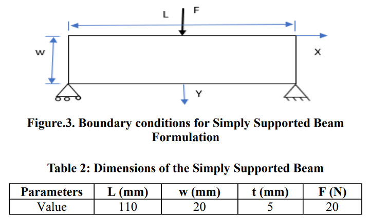
Boundary conditions for simply supported beam formulation
The figure above shows the boundary conditions for the beam, while the table provides its dimensions. The simply supported configuration is one of the most common loading scenarios in structural engineering, making this study particularly relevant to real-world applications.
Finite Element Analysis Results
In order to see displacement and stress distribution, the team performed a finite element analysis. The contour plots above and below illustrate these measurements, respectively, for the beam’s load case.

Displacement plot solution for simply supported beam
The displacement plot shows how much the beam deforms under load. In a topology-optimized design, you want to minimize this displacement while using less material. The contour helps identify which areas contribute most to the beam’s stiffness and which areas can be removed without significantly affecting performance.
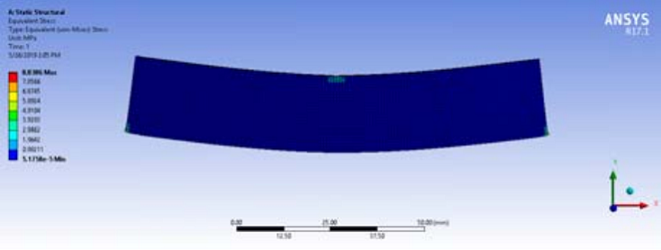
Von misses stress distribution for simply supported beam
The von Mises stress distribution reveals where the beam experiences the highest stress levels. Areas with high stress must retain material, while low-stress areas can be reduced or eliminated. This information is crucial for the optimization algorithm to determine the final material layout.
Element Density Distribution
In the element density distribution plot below, red equals elements that have a density equal to one, which are the part’s load bearing elements. The large blue areas of the part are elements with a density equal to zero, which will likely “need material removal as they have negligible effect on the performance of the part and can be neglected from optimized design.”
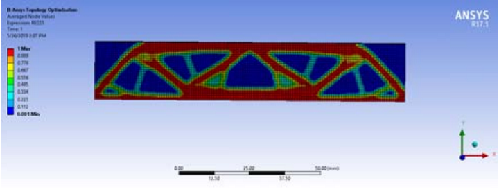
Element density distribution plot for simply supported beam
The other colors (values) in the plot, such as green and yellow, represent the intermediate density, which is “penalized to obtain a practical design” with the SIMP method. These intermediate values represent areas where the algorithm is undecided about whether material should exist, and the penalization scheme helps drive these toward either 0 (void) or 1 (solid).
From Digital Model to Physical Part: FDM 3D Printing
Due to their complexity, these topology optimized designs would be impossible to make using conventional methods of manufacturing, which is why FDM 3D printing was so useful – the technology is capable of making these types of complex shapes.
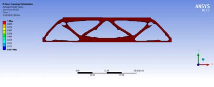
Topology optimized simply supported beam
The final optimized design showcases the power of topology optimization. Notice how the material is concentrated in areas that carry the most load – particularly near the supports and the load application point. The organic, lattice-like structure is characteristic of topology-optimized parts and provides excellent strength-to-weight ratio.
FDM Printing Considerations
When printing topology-optimized parts with FDM, several factors must be considered:
- Print Orientation: The orientation of the part on the build plate significantly affects strength. See also: Best Budget 3D Printer Upgrades That Actually Impr…. Always orient the part so that the primary load direction aligns with the layer direction to maximize strength.
- Infill Settings: For topology-optimized parts, you may use lower infill percentages since the optimization already handles material distribution. However, ensure sufficient perimeter layers for structural integrity.
- Support Structures: Complex geometries often require support material. Use tree supports or custom supports to minimize material usage and post-processing time.
- Material Choice: Choose materials based on the application requirements. PLA works for prototypes, while PETG, ABS, or Nylon are better for functional parts requiring higher strength or temperature resistance.
- Print Quality: High-quality prints are essential for accurate mechanical performance. Ensure proper bed leveling, temperature settings, and print speed for optimal results.

FDM 3D printed topology optimized simply supported beam
“This paper shows an example of the capability of fused deposition modelling 3D printing process by using Topology optimization methods such as Solid Isotropic material with Penalization,” the researchers concluded.
Practical Applications of Topology Optimization
The techniques demonstrated in this study have wide-ranging applications across industries:
Aerospace
Weight reduction is critical in aerospace applications. Topology optimization can reduce component weight by 30-50% while maintaining or improving performance. Examples include:
- Aircraft brackets and fittings
- Satellite components
- Drone frame parts
- Turbine blade components
Automotive
Automotive manufacturers use topology optimization to:
- Reduce vehicle weight for improved fuel efficiency
- Optimize chassis components
- Design lightweight suspension parts
- Create optimized engine components
Medical
In medical applications, topology optimization helps create:
- Customized implants with optimal load distribution
- Lightweight prosthetic components
- Surgical instruments with improved ergonomics
- Dental aligners and orthodontic devices
Consumer Products
Even everyday products benefit from topology optimization:
- Lightweight backpack frames
- Optimized bicycle components
- Ergonomic tool handles
- Custom sports equipment
Getting Started with Topology Optimization
For makers and engineers interested in trying topology optimization, several software options are available:
Commercial Software
- ANSYS Mechanical: Industry-leading FEA software with topology optimization capabilities. Professional-grade, with comprehensive analysis tools.
- SolidWorks Simulation: Integrated topology optimization within the CAD environment. User-friendly for those already using SolidWorks.
- Autodesk Fusion 360: Offers topology optimization in its generative design tools. Free for personal use and startups.
- nTopology: Specialized software for advanced topology optimization and generative design. Particularly good for lattice structures.
Open Source and Free Tools
- TopOpt: Open-source topology optimization code from Technical University of Denmark. Research-grade but powerful.
- OpenFOAM: Open-source CFD software that can be extended for topology optimization.
- Gmsh: Finite element mesh generator that works with various optimization codes.
Recommended Workflow
- Define Requirements: Clearly specify loading conditions, constraints, and performance goals
- Create CAD Model: Design the initial shape and design space
- Set Up Optimization: Define objective functions and constraints
- Run Optimization: Let the algorithm find optimal material distribution
- Analyze Results: Evaluate stress distribution and performance
- Refine Design: Adjust parameters if necessary and re-run
- Prepare for Printing: Optimize for FDM printing (orientation, supports, etc.)
- Print and Test: Fabricate the part and validate performance
Frequently Asked Questions
What is the main advantage of topology optimization for 3D printing?
Topology optimization allows you to create parts that use significantly less material while maintaining or improving structural performance. This results in lighter parts, reduced material costs, and often better strength-to-weight ratios compared to traditionally designed parts.
Do I need expensive software to do topology optimization?
Not necessarily. While professional tools like ANSYS and nTopology offer advanced features, there are free and open-source options available. Autodesk Fusion 360 offers topology optimization in its free personal license, and research codes like TopOpt are freely available for those comfortable with programming.
How long does topology optimization take?
Complexity varies widely. Simple parts might optimize in minutes, while complex assemblies can take hours or even days. Factors affecting time include mesh resolution, computational resources, optimization method, and convergence criteria. Cloud computing can significantly speed up the process.
Can I use any 3D printing method with topology-optimized parts?
While FDM is excellent for topology-optimized parts, other methods like SLA (resin), SLS (powder), and DMLS (metal) also work well. Each method has advantages: SLA offers higher resolution, SLS doesn’t require supports, and DMLS can produce metal parts with excellent mechanical properties.
How much material can I save with topology optimization?
Material savings typically range from 30-70%, depending on the application, design constraints, and optimization goals. Some studies report even higher savings for specific applications. The exact amount depends on factors like loading conditions, performance requirements, and manufacturing constraints.
Is topology optimization only for mechanical engineers?
Not at all! While mechanical engineers benefit greatly, designers, makers, and hobbyists can also use topology optimization. Modern software has become more user-friendly, and even those without deep engineering knowledge can produce excellent results. The key is understanding the basic principles and your specific application requirements.
What are the limitations of topology optimization?
Limitations include: computational cost for complex problems, the need for accurate loading data, potential for designs that are difficult to manufacture (though this is less of an issue with 3D printing), and the risk of over-optimization that might not account for real-world factors like assembly constraints or thermal effects.
How do I validate a topology-optimized design?
Validation involves: (1) Analytical verification using FEA software, (2) Physical testing of prototype parts, (3) Comparison with traditional designs, and (4) Long-term durability testing if the part will be used in critical applications. Always test under conditions that mimic real-world usage.
Conclusion
The combination of topology optimization and FDM 3D printing represents a powerful toolset for creating optimized mechanical parts. As demonstrated by the HBTU research team’s study on simply supported beams, this approach can significantly reduce material usage while maintaining or improving structural performance.
Whether you’re a professional engineer looking to optimize production parts or a maker interested in pushing the boundaries of 3D printing, topology optimization offers exciting possibilities. As software becomes more accessible and FDM printers continue to improve, we can expect to see increasingly sophisticated and efficient designs across all industries.
The key takeaway is that topology optimization isn’t just about making parts lighter—it’s about making them smarter. By letting algorithms determine where material is truly needed, we can create designs that are optimized for their specific purpose, taking full advantage of 3D printing’s unique capabilities.
References and Further Reading
- Verma, U., Gupta, V., & Bhaskar, J. (2019). Topological Optimization of Simply Supported Beam for Fused Deposition Modelling Process. Krishisanskriti Publications.
- Bendsøe, M. P., & Sigmund, O. (2003). Topology Optimization: Theory, Methods, and Applications. Springer.
- Zhou, M., & Rozvany, G. I. N. (1991). The COC algorithm, Part II: Topological, geometrical and generalized shape optimization. Computer Methods in Applied Mechanics and Engineering, 89(1-3), 309-336.
- ANSYS. (2020). Topology Optimization in ANSYS Mechanical. ANSYS Documentation.
- Eschenauer, H. A., & Olhoff, N. (2001). Topology optimization of continuum structures: A review. Applied Mechanics Reviews, 54(4), 331-390.
Frequently Asked Questions
What is the best 3D printing filament for beginners?
PLA is the best starting filament — it prints easily at 190-220°C without an enclosure and produces good results. Once comfortable, PETG offers better strength and temperature resistance for functional parts.
How do I choose the right filament?
Consider the application: PLA for display models, PETG for functional parts, ABS/ASA for heat/sunlight exposure, TPU for flexible parts, and specialty filaments for engineering applications. Each has specific printer requirements.
What temperature should I print different filaments at?
PLA: 190-220°C nozzle / 50-60°C bed. PETG: 220-250°C / 70-80°C. ABS: 230-260°C / 100-110°C (enclosure needed). Nylon: 240-270°C / 70-90°C. Always check manufacturer recommendations for specific brands.
📌 Related Articles
- Best 3D Printer Upgrades That Actually Improve Print Quality: Complete 2026 Guide
- Best Budget 3D Printer Upgrades That Actually Improve Print Quality: Belts, Springs, Hotends & More
- ABS 3D Printing Settings Guide: Temperature, Enclosure, and Cooling for Strong Parts
- Bambu Lab A1 vs Elegoo Centauri Carbon: Full Specs Comparison & Buyer’s Guide
- 3D Printing Safety Equipment Guide: Respirators, Gloves, and Ventilation for 2026