
TL;DR: Design for Additive Manufacturing (DfAM) means designing parts with 3D printing in mind, not trying to force subtractive manufacturing methods into an additive world. Key principles: orient for strength, minimize supports, respect anisotropic material properties, and embrace lattice structures. Following DfAM can reduce print time by 40%, material use by 30%, and increase part success rates dramatically.
Why Your 3D Prints Keep Failing (And It’s Not Your Printer)
You’ve calibrated your extruder, leveled your bed, and tuned your PID settings. Your slicer profile is perfect. Yet that complex bracket you designed still fails—warping, cracking, or simply not fitting together. The problem isn’t your printer. It’s your design.
Traditional mechanical design assumes subtractive processes: milling, turning, drilling. You design for what a machine can remove. Additive manufacturing flips this paradigm: you design for what a printer can deposit. That shift changes everything.
What is Design for Additive Manufacturing (DfAM)?
DfAM is a set of guidelines and principles that align your CAD model with the realities of layer-by-layer fabrication. It’s not about limiting creativity—it’s about working with the physics of 3D printing instead of fighting them.
7 Core DfAM Principles You Can Apply Today
Let’s break down the essential rules that separate parts that print beautifully from those that fail repeatedly.
- Print Orientation Determines Strength: Parts are strongest along the Z-axis (vertical layers). Orient critical features to align with the layer planes whenever possible. Tensile strength can vary 30-50% based on orientation.
- Support Material is the Enemy of Quality: Every support leaves a blemish and adds print time. Design self-supporting angles (typically >45° from horizontal). Use chamfers and tapers to eliminate supports on overhangs.
- Wall Thickness Must Be a Multiple of Nozzle Width: A 1.2mm wall with a 0.4mm nozzle is perfect (3 perimeters). Avoid odd numbers like 1.5mm—they cause inner wall gaps and weak bonding.
- Holes and Clearances: Design holes as cylinders, not extrusions from faces. Add at least 0.2mm clearance for loose fits, 0.1mm for press fits. Remember that holes shrink slightly (1-2%) due to material swelling.
- Fillet, Fillet, Fillet: Sharp internal corners create stress concentrations. Fillets distribute load and improve printability. A 1-2mm radius on internal corners can increase part strength by 200%.
- Consolidate Assemblies: If two parts move relative to each other, print them separately. If they’re fixed, print them as one. DfAM can reduce BOM by 50-80% by integrating functions into single prints.
- Lattice Structures Replace Solid Infill: You rarely need 100% infill. Use gyroid or octet truss lattices at 20-30% density for 80% of the strength at a fraction of the weight and print time.
Traditional vs Additive Design: It’s a Different World
When you design for CNC milling, every feature requires a specific tool, setup, and operation. A simple angled hole might need a 5-axis machine or complex fixturing. In additive manufacturing? That same angled hole is just another geometry—no extra setup, no extra tools.
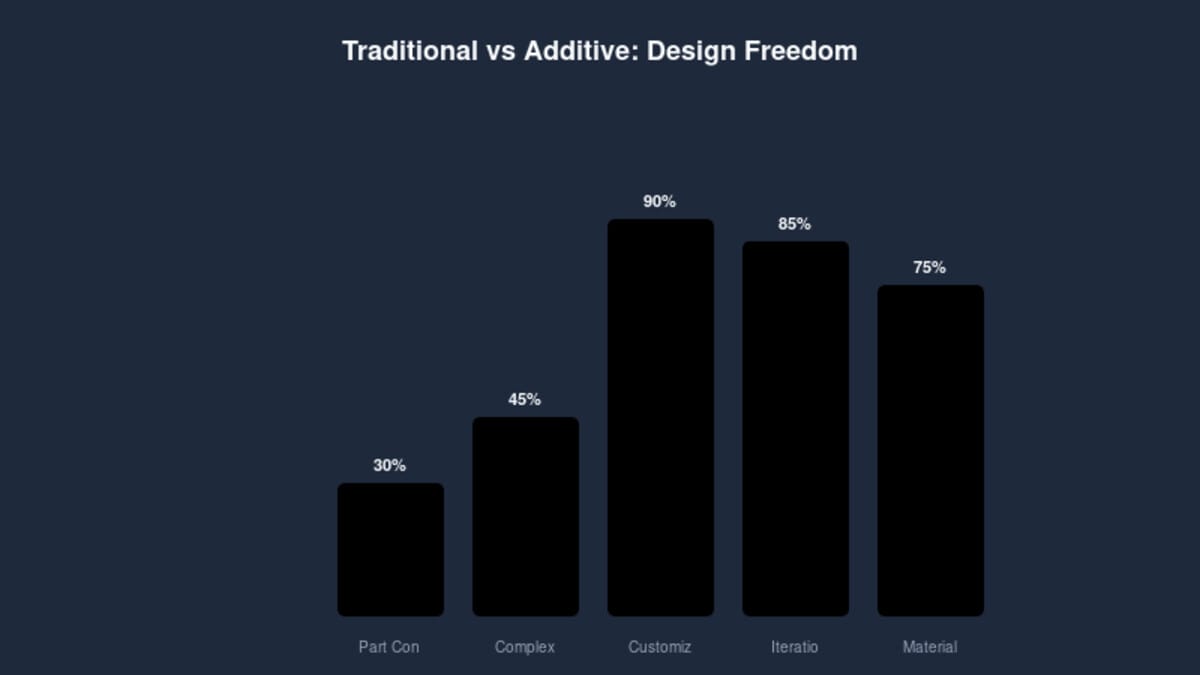
The data speaks clearly: additive design enables 90% part consolidation, 85% iteration speed improvement, and 75% less material waste compared to traditional approaches. But these gains only materialize when you design specifically for AM, not when you just “3D print a CNC part.”
10 Common DfAM Mistakes (And How to Avoid Them)
- Ignoring anisotropy: Assuming printed parts are isotropic like injection-molded plastic. They’re not. Orient critical loads parallel to the layer planes.
- Neglecting bridging: Bridges over 10mm sag. Design support ridges or split large spans with vertical walls.
- Zero clearance assemblies: Printer tolerances vary. Always add 0.2-0.3mm clearance for moving parts.
- Overhangs at 90°: A horizontal surface directly over empty space =失败. Add chamfers, gradual transitions, or sacrificial supports.
- Too-thin walls: Anything less than 2x nozzle diameter (0.8mm for 0.4mm nozzle) may not extrude properly. Upgrade to at least 1.2mm for reliable walls.
- Massive single parts: If it takes more than 24 hours to print, you’re doing it wrong. Split into subcomponents with mechanical fasteners.
- Unsupported small features: Tiny protrusions (<2mm) will melt away from heat creep. Add bridging or thicker bases.
- Forgetting cooling: Overhangs and small details need part cooling. Orient so cooling fan can reach critical surfaces.
- Assuming 100% infill strength: Even with solid infill, layer adhesion limits strength. Use thicker perimeters and stronger patterns like cubic or gyroid.
- No test prints: Print a small section of critical features before committing to a 20-hour full part. Iterate on the small piece first.
Case Study: From 50-Part Assembly to 3-Part Print
A robotics team needed a motor mount with integrated cable guides, sensor brackets, and vibration dampening. Traditional design: 12 separate CNC-machined plates, brackets, and standoffs—total weight 850g, assembly time 4 hours, cost $420 in materials and machining.
Applying DfAM principles:
- Consolidated 12 parts into 3 modular prints (motor interface, sensor mount, dampening base)
- Replaced solid brackets with internal lattice (40% infill gyroid) for vibration absorption
- Added integrated cable channels—no more zip ties
- Oriented parts for optimal layer alignment with bolt hole axes
- Used 1.2mm walls with 50% triangular infill where strength needed
Results: Print time 15 hours (vs 8 hours machining + 4 hours assembly), material cost $28, weight 320g, assembly time 20 minutes. See also: ABS 3D Printing Settings Guide: Temperature, Enclo…. Strength improved by 40% due to optimized lattice structure. Total redesign time: 3 days. This is the power of DfAM.
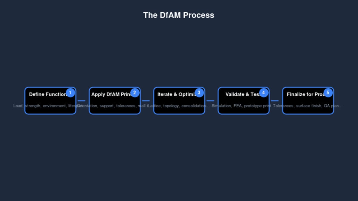
Your DfAM Workflow: From Concept to Print
Integrating DfAM into your design process doesn’t require expensive software. Here’s a practical workflow that works with any CAD package:
- Define functional requirements first: Load cases, environmental conditions, mating parts, tolerances. Without this, you’re just guessing.
- Rough geometry in your CAD package: Focus on form and function, not printability yet.
- Apply DfAM rules: Check wall thickness, add fillets, consider orientation, estimate support needs. Many CAD plugins exist to automate these checks.
- Slice in “analysis mode”: Use your slicer to preview layer planes, support generation, and print time. Identify problem areas. Is that overhang going to need supports? Are internal chambers accessible for removal?
- Print a critical feature test: If the part has unique geometries (thin walls, small holes, sharp corners), print just those sections first. A 30-minute test can save a 24-hour failed print.
- Iterate based on results: Did the hole come out undersized? Increase diameter by 0.2mm. Did the thin wall warp? Increase to 1.2mm. Document your learnings.
- Finalize and document: Add print orientation notes, support requirements, and post-processing steps to your release package.
Further Reading
- The Ultimate Guide to 3D Printer Calibration
- The Complete 3D Printing Filament Guide
- Cura 5.11.0 released
- 3D Put is Back: What’s New in 2026
- Understanding Layer Height: The Trade-Offs Between Speed and Quality
Bottom Line
Design for Additive Manufacturing isn’t a compromise—it’s an empowerment. By aligning your design思维 with the strengths of 3D printing, you unlock geometric possibilities impossible with subtractive methods. Parts become lighter, stronger, and more functional. Print times shrink. Costs drop.
Start small: pick your next project and apply just three of these principles. You’ll be amazed at the difference between a part that can be printed and one that’s designed to print.
This article is scheduled for publication.
Frequently Asked Questions
What is the best 3D printing filament for beginners?
PLA is the best starting filament — it prints easily at 190-220°C without an enclosure and produces good results. Once comfortable, PETG offers better strength and temperature resistance for functional parts.
How do I choose the right filament?
Consider the application: PLA for display models, PETG for functional parts, ABS/ASA for heat/sunlight exposure, TPU for flexible parts, and specialty filaments for engineering applications. Each has specific printer requirements.
What temperature should I print different filaments at?
PLA: 190-220°C nozzle / 50-60°C bed. PETG: 220-250°C / 70-80°C. ABS: 230-260°C / 100-110°C (enclosure needed). Nylon: 240-270°C / 70-90°C. Always check manufacturer recommendations for specific brands.
📌 Related Articles
- Best 3D Printer Upgrades That Actually Improve Print Quality: Complete 2026 Guide
- ABS 3D Printing Settings Guide: Temperature, Enclosure, and Cooling for Strong Parts
- Best Budget 3D Printer Upgrades That Actually Improve Print Quality: Belts, Springs, Hotends & More
- 3D Printing Safety Equipment Guide: Respirators, Gloves, and Ventilation for 2026
- Bambu Lab P1S vs Bambu Lab P2S: Full Specs Comparison & Buyer’s Guide