Table of Contents
- Why Extruder Calibration Matters
- What You’ll Need
- Understanding E-Steps and M-Steps
- Step 1: Prep Your Printer
- Step 2: Mark and Measure Your Filament
- Step 3: Extrude a Test Length
- Step 4: Calculate Your New E-Step Value
- Step 5: Save and Re-Test
- Firmware-Specific Instructions
- Common Problems and Troubleshooting
- Extruder Hardware Upgrades That Improve Consistency
- Flow Rate vs. E-Steps: Knowing the Difference
- How Often Should You Recalibrate?
- Final Thoughts
Why Extruder Calibration Matters
If your 3D prints suffer from under-extrusion, stringing, gaps between perimeters, or mysterious dimensional inaccuracies, there’s a good chance your extruder steps-per-millimeter (E-steps) are off. Extruder calibration is one of the most impactful tuning steps you can perform on any FDM 3D printer, yet it’s something many makers skip entirely.
E-step calibration ensures that when your printer’s firmware commands the extruder to push exactly 100 mm of filament, the extruder gear actually feeds 100 mm — not 94 mm or 108 mm. This single calibration directly affects print quality, dimensional accuracy, and overall reliability. Think of it as the foundation upon which every other print tuning parameter rests. If your extrusion is wrong at the source, no amount of temperature tweaking or retraction tuning will fully compensate.
In this guide, we’ll walk through the entire extruder calibration process step by step, covering Marlin, Klipper, and RepRapFirmware. Whether you’re running a stock Creality Ender 3, a modified Prusa, or a custom Voron build, this process applies to your setup.
What You’ll Need
Before starting the calibration, gather a few basic tools:
- A ruler or digital caliper — A caliper is strongly preferred for accurate measurements. You’ll be measuring filament distances down to the millimeter, and a good caliper makes this much easier and more reliable.
- A permanent marker — For marking your filament before the test extrusion.
- Your printer’s control interface — This could be Pronterface, OctoPrint, Mainsail/Fluidd, or your printer’s LCD menu. You need to be able to send G-code commands.
- About 200 mm of filament — Any filament works, but use the type you print with most often for the most relevant results.
- A notebook or spreadsheet — To record your measurements and calculations.
That’s it. No specialty tools, no disassembly, and no cost. This is one of the highest-return calibrations you can do on a 3D printer.
Understanding E-Steps and M-Steps
Before diving into the process, it helps to understand what E-steps actually represent. Your printer’s stepper motor doesn’t understand millimeters — it understands steps. The E-step value tells the firmware how many stepper motor steps are required to feed exactly 1 mm of filament through the extruder.
This value depends on several hardware factors:
- Stepper motor steps per revolution — Usually 200 full steps (1.8° per step) or 400 full steps (0.9° per step).
- Microstepping setting — Typically 16x on most printer boards, but can be 32x or higher on newer boards.
- Gear ratio — Direct-drive extruders are often 1:1, while geared extruders (like the BMG or Orbiter) have ratios like 3:1 or 7:1.
- Hob gear diameter — The effective diameter of the drive gear that grips the filament.
The default E-step value in most firmware is typically calculated from these specifications. For example, a standard Creality extruder with a 6.9 mm drive gear at 16x microstepping gives roughly 93 steps/mm. A Bondtech BMG extruder with its 3:1 gear ratio uses a value around 415 steps/mm.
However, theoretical calculations don’t always match reality. Manufacturing tolerances in the drive gear, filament compression, and wear on the hob gear all introduce small discrepancies. That’s why empirical calibration — actually measuring what comes out — is so important.
Step 1: Prep Your Printer
Heat the Hotend
Your hotend needs to be at printing temperature so the filament can actually flow when extruded. Set it to whatever temperature you normally print at for the filament you’re using. For PLA, that’s typically 200–210°C. For PETG, 230–250°C.
Do not run extrusion commands with a cold hotend. This will jam your extruder and potentially damage your PTFE tube or heat break.
Remove Any Retraction Compensation
If you’re using linear advance (Klipper’s pressure advance or Marlin’s Linear Advance), disable it during calibration. These features alter extrusion behavior and will throw off your measurements.
In Marlin, send: M900 K0
In Klipper, temporarily comment out or set pressure_advance: 0 in your config and restart.
Ensure the Extruder Is Loaded
Make sure filament is loaded all the way to the nozzle. You should be able to extrude filament manually before starting the test.
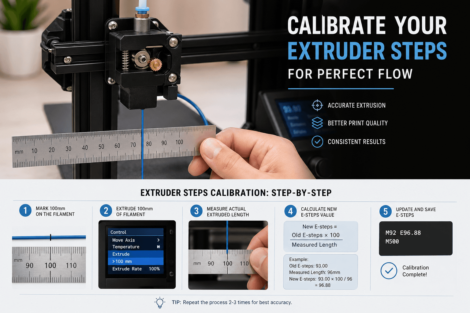
Step 2: Mark and Measure Your Filament
This is where precision matters. Follow these steps carefully:
- Identify the extruder entry point. Look at where the filament enters your extruder assembly — this is the point where the drive gear grips the filament.
- Measure 120 mm from the entry point along the filament toward the filament spool. Use your ruler or caliper to mark this point precisely with your permanent marker. Make the mark thin and clear — you’ll need to see it clearly after the test.
- Record this starting measurement. Write down exactly 120 mm (or whatever you measured). This is your “commanded” starting distance from the extruder entry.
The key here is consistency. Always measure from the same reference point — the exact spot where the filament meets the extruder body or PTFE fitting. If your reference point moves between marking and measuring, your calibration will be wrong.
Step 3: Extrude a Test Length
Now we’ll command the printer to extrude a known length and see how much actually moves.
- Send the extrusion command. Command the printer to extrude exactly 100 mm of filament. Use your printer’s control interface to send:
G91 ; Relative positioning
G1 E100 F100 ; Extrude 100mm at 100mm/min
The slow speed (F100 = 100 mm/min) is important — it mimics normal printing speeds and avoids slipping that can occur at very fast extrusion rates.
- Watch the filament. As the extruder runs, observe the filament spool feeding smoothly and no slipping at the drive gear. If you hear clicking or grinding, you have a separate issue (tension, partial jam, or worn gear) that needs fixing before calibration.
- Wait for completion. Let the extrusion finish completely before touching anything.
Step 4: Calculate Your New E-Step Value
Now measure how much filament actually moved:
- Measure the distance from your extruder entry point to the mark you made earlier. If the extruder fed exactly 100 mm, the mark should now be roughly 20 mm from the entry point (120 mm original – 100 mm extruded = 20 mm remaining).
- Calculate actual extrusion: Subtract your new measurement from the original mark distance.
Actual Extrusion = Original Mark Distance - Remaining DistanceFor example: If your mark is now 28 mm from the entry point instead of 20 mm, only 92 mm was actually extruded (120 – 28 = 92).
- Calculate your new E-step value using this formula:
New E-Steps = Current E-Steps × (Commanded Extrusion ÷ Actual Extrusion)Example: If your current E-steps are 93.0, you commanded 100 mm, but only 92 mm actually extruded:
New E-Steps = 93.0 × (100 ÷ 92) = 93.0 × 1.087 = 101.1
Round to one decimal place for most firmwares. This new value compensates for the discrepancy between theoretical and actual extrusion.
Step 5: Save and Re-Test
Don’t just set your new E-step value and start printing — verify it first.
- Set the new E-step value temporarily (firmware-specific commands in the next section).
- Repeat the mark-and-measure test from Step 2 through Step 4 using the new value.
- Check the results. You should now be very close to 100 mm actual extrusion. If you’re within ±0.5 mm (99.5 to 100.5 mm actual), you’re done. That’s less than 0.5% error, which is excellent.
- If still off, iterate. Run the calculation one more time with your updated value. Most people nail it in two rounds.
- Save permanently once satisfied. Write the value to your firmware’s persistent storage so it survives power cycles.
Firmware-Specific Instructions
Marlin Firmware
Marlin is the most common firmware on consumer 3D printers. Here’s how to read and set E-steps:
Check current E-steps:
M503 ; Dump all settings — look for "M92 E" in the outputSet new E-steps temporarily:
M92 E101.1 ; Replace with your calculated valueSave to EEPROM:
M500 ; Store settings in EEPROMAfter saving, you can verify with M503 again to confirm the new value persisted. Some older Marlin versions use M500 followed by M501 to reload and confirm.
Klipper Firmware
Klipper handles things a bit differently. E-step calibration is stored in your printer.cfg file rather than EEPROM.
Check current rotation_distance (Klipper’s equivalent):
Look in your printer.cfg under the [extruder] section for rotation_distance. The relationship between E-steps and rotation_distance is:
rotation_distance = <full_steps_per_rotation> × <microsteps> / <e_steps>To set new E-steps in Klipper:
- Calculate your new rotation_distance:
new_rotation_distance = old_rotation_distance × (actual_extrusion ÷ commanded_extrusion)Note: this is the inverse of the Marlin formula because Klipper’s rotation_distance is inversely proportional to E-steps.
- Edit your
printer.cfgand update the value in the[extruder]section. - Restart the firmware:
FIRMWARE_RESTART
Klipper also has a built-in calibration command that automates much of this. You can use CALIBRATE_EXTRUDER if your configuration supports it, though the manual method above gives you more control and understanding of what’s happening.
RepRapFirmware
For Duet and other RepRapFirmware-based boards:
Check current E-steps:
M92 ; Report current steps/mm for all axesSet new E-steps:
M92 E101.1 ; Set new valueSave to config-override.g:
M500 ; Save (writes to config-override.g)Alternatively, you can edit your config.g file directly on the SD card to make the change permanent in your base configuration.
Common Problems and Troubleshooting
Slipping Extruder Gear
If the drive gear is slipping on the filament during your test extrusion, you’ll get inconsistent measurements. You might notice the filament advancing in jerky bursts rather than a smooth, steady feed. This is usually caused by:
- Insufficient spring tension — The idler bearing isn’t pressing the filament firmly enough against the drive gear. Tighten the tension screw on your extruder.
- Worn or clogged hob gear — Over time, the teeth on the drive gear fill with filament dust and lose grip. Clean the gear with a brass brush, or replace it if the teeth are visibly worn flat.
- Filament diameter inconsistency — Very cheap filament can vary enough in diameter to cause intermittent grip issues.
Inconsistent Results Between Tests
If you run the calibration three times and get three different results, something is mechanically inconsistent. Check for:
- Loose grub screw on the extruder gear (the gear is slipping on the motor shaft)
- PTFE tube that isn’t fully seated, introducing variable resistance
- Partially clogged nozzle creating variable back-pressure
- Filament spool that doesn’t rotate freely, creating intermittent tension
Fix the mechanical issue first, then calibrate. Calibration cannot compensate for mechanical problems.
Large Discrepancy from Default
If your calculated E-step value is more than about 15% off from the default, something unusual is going on. Double-check your math first, then investigate whether:
- Your microstepping setting matches what the firmware expects
- The correct gear ratio is configured (especially for geared extruders)
- The drive gear is the correct diameter for the configured value
A large mismatch usually indicates a configuration error rather than a normal calibration adjustment.
Extruder Hardware Upgrades That Improve Consistency
If you find yourself recalibrating frequently or struggling with inconsistent extrusion, upgrading your extruder hardware can make a significant difference. Here are some upgrades worth considering:
Dual-Drive Extruders
Stock single-gear extruders (like the basic Creality design) grip the filament on only one side, which can lead to inconsistent feed rates, especially with flexible filaments. Dual-drive extruders like the BMG, Orbiter, or dual-gear extruder upgrade kits grip the filament from both sides, providing much more consistent feeding and reducing the need for frequent recalibration.
Better Drive Gears
Replacing a worn stock gear with a precision-machined hob gear from Bondtech or similar manufacturers can dramatically improve grip consistency. This is especially important if you print a lot with abrasive filaments (carbon fiber, glow-in-the-dark) that wear down standard brass gears quickly.
Quality Filament
Not all filament is created equal. Filament with consistent diameter (1.75 mm ± 0.02 mm) feeds more predictably through any extruder. Premium PLA filament from reputable brands tends to have tighter tolerances, which directly translates to more consistent extrusion and less need for mid-print flow adjustments.
Flow Rate vs. E-Steps: Knowing the Difference
A common point of confusion is the relationship between E-steps and flow rate (sometimes called extrusion multiplier). Here’s the key distinction:
E-steps are a hardware calibration. They tell the firmware how many motor steps correspond to 1 mm of filament feed. This value should be set once and left alone unless you change hardware.
Flow rate is a slicer setting (expressed as a percentage) that multiplies the amount of filament the slicer commands. If your E-steps are correct but prints still show minor over- or under-extrusion, you fine-tune with flow rate in your slicer — typically between 95% and 105%.
The correct order of operations is:
- Calibrate E-steps first — this is your hardware baseline.
- Then fine-tune flow rate in your slicer — this compensates for slicer-specific factors like slight differences between actual and nominal filament diameter, and the way your particular slicer calculates extrusion width.
Never use flow rate to compensate for wrong E-steps. You’d end up with incorrect pressure advance values, inconsistent retraction, and different behavior at different print speeds.
How Often Should You Recalibrate?
In practice, you only need to recalibrate E-steps when:
- You change extruder hardware — New gear, new motor, new extruder assembly entirely.
- You switch between significantly different filaments — Going from rigid PLA to soft TPU can change effective feed behavior.
- You notice print quality degradation — If previously good prints start showing under-extrusion, it’s worth checking.
- After significant wear — If you’ve printed hundreds of hours with abrasive filaments, the hob gear may have worn enough to change the effective diameter.
For most users, a single careful calibration when setting up a new printer (or after upgrading the extruder) is sufficient. The value should remain stable for months under normal use.
Final Thoughts
Extruder E-step calibration is one of those foundational tuning steps that pays dividends across every single print you make. It takes about 15 minutes, requires no special tools beyond a ruler or caliper, and can transform print quality from “mostly okay” to remarkably consistent.
The process is the same regardless of your printer model or firmware — mark the filament, extrude a known length, measure the result, and calculate the correction. The firmware-specific details only affect how you save the value.
Once calibrated, you’ll find that other tuning tasks become easier too. Retraction settings, pressure advance, and flow rate adjustments all work more predictably when your extrusion baseline is correct. It’s the calibration that makes every other calibration better.
If you’ve been putting this off, grab a marker and your caliper and do it now. Your future prints will thank you.