
Quick Answer: What is Side-Branching in LPBF?
Side-branching is a critical microstructural phenomenon in laser powder-bed fusion (LPBF) where crystal growth extends sideways from the primary growth direction, creating complex grain structures. This process significantly affects the mechanical properties of 3D-printed metal parts, influencing everything from strength to fatigue resistance. Researchers have found that side-branching occurs particularly at melt pool boundaries and can be controlled through scanning strategy selection, offering a pathway to optimize part quality in additive manufacturing.
Introduction to LPBF Microstructure Control
Laser powder-bed fusion (LPBF) has revolutionized metal additive manufacturing, enabling the production of complex geometric components with unprecedented design freedom. However, the journey from digital model to high-quality mechanical part depends critically on understanding and controlling the solidification microstructure. When a laser beam interacts with metal powder, it creates a transient melt pool that rapidly solidifies, forming grains that determine the final material properties. Recent research published in Nature Communications has shed new light on one of the most important mechanisms governing this process: side-branching.
As manufacturing of industrial parts via 3D printing and additive manufacturing processes becomes critical to an increasing number of applications today, suitable microstructures are required for quality parts. The mechanical performance, thermal stability, and corrosion resistance of LPBF-fabricated components all depend on the solidification microstructure that develops during printing. This makes understanding microstructural control not just an academic exercise, but a practical necessity for engineers and manufacturers seeking to harness the full potential of additive manufacturing technology.
Understanding Side-Branching in Metal 3D Printing
Side-branching refers to the phenomenon where crystals, initially growing in a primary direction, develop secondary growth arms that extend perpendicular to that direction. Think of it like a tree growing upward (primary growth) while sending branches out to the sides (secondary growth). In LPBF, this occurs at the solid-liquid interface during solidification and is influenced by thermal gradients, cooling rates, and compos variations in the melt pool.
Although 3D printing has been around since the 80s, it is still a relatively new technology—and especially to the mainstream. Benefits abound, but so do a variety of challenges. While porosity is an issue of ongoing study, here the authors address the epitaxial growth of crystals and how it affects development of microstructures. The study reveals that side-branching is not just a random occurrence but a predictable phenomenon that can be manipulated to achieve desired microstructural outcomes.
Research Methodology: Advanced Characterization Techniques
In studying solidification microstructure, the researchers evaluated thermal parameters to better understand what types of mechanisms are behind the development of microstructures, specifically at certain areas of melt pools. The research team employed several sophisticated characterization techniques to unravel the complex solidification processes:
- Electron Backscatter Diffraction (EBSD): Provided detailed mapping of crystal orientations and grain structure
- X-ray Diffraction: Confirmed phase composition and crystallographic information
- Finite Element Analysis (FEA): Modeled thermal profiles and melt pool dynamics
- Chemical Etching: Revealed cellular and dendritic structures invisible to the naked eye
During their research, the authors found that X-ray diffraction revealed two alloys made up of one face-centered (FCC) cubic phase—both in the ‘as-received powder’ and in the LPBF builds. This finding is significant because it establishes that the fundamental crystallographic structure is preserved during the printing process, even as the microstructure undergoes dramatic reorganization.
Key Findings: From Cellular to Dendritic Growth
“Because cells can be only seen after chemical etching, the undulated surface results from the chemical perturbation. This indicates that although the high cooling rate can prohibit the formation of secondary arms, there are still solid-liquid interface instabilities in the direction orthogonal to the primary growth direction,” explained the researchers. “The presence of such side instabilities indicates that cells are in the transition from cellular to dendritic growth.”
This observation is particularly important because it reveals that LPBF materials often exist in a metastable state between cellular and dendritic growth regimes. The high cooling rates characteristic of LPBF (up to 10^6 K/s) typically favor cellular solidification, but the complex thermal conditions at melt pool boundaries can create localized regions where dendritic side-branching becomes possible. Understanding this transition state is crucial for predicting and controlling final grain structures.
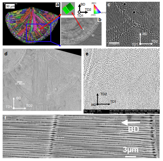
Solidification microstructure in a single-track and in a multi-layer build of HEA. a EBSD inverse pole figure (IPF) map along build direction (BD) and b secondary electron image of cells in a single track of HEA. c Cells in regions far away from the build/substrate interface. d–f Solidification microstructure in 316L fabricated by a Renishaw: d Cells in a melt pool of 316L, e and f Transverse and longitudinal sections of a cell domain within a melt pool, respectively.
The Relationship Between Porosity and Microstructure
Porosity has long been recognized as one of the most common defects in LPBF parts, but this research reveals an important interaction between porosity and microstructural development. In regards to impacts caused by porosity, the researchers noted that change in length scale was the result of the high cooling rate after the depositing of a new melt pool—with cell refinement found at fusion lines between two well consolidated weld beads and a lack of pores.
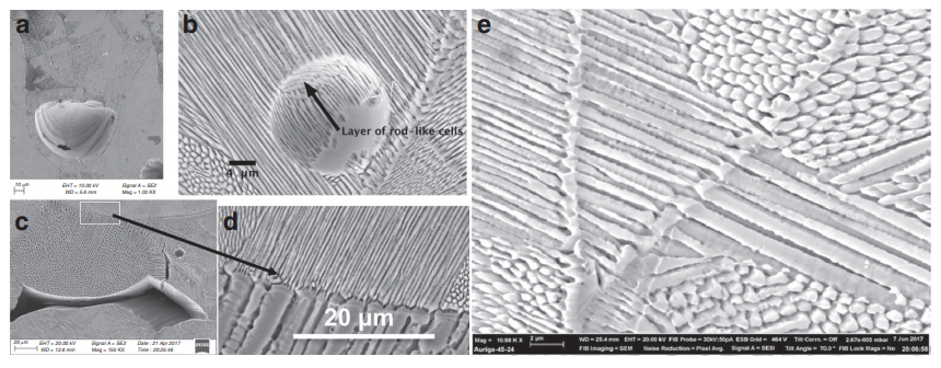
Porosity and solidification microstructure in AM 316L. a Keyhole pore. b Layers of fine cells in a region containing a fine spherical entrapped gas pore. c Solidification microstructure surrounding a lack-of-fusion pore. d Zoom-in region on the center top of c showing a sharp change in cell spacing. e Cell refinement occurred twice at two consecutive fusion lines.
The study identified three main types of porosity, each with distinct effects on the surrounding microstructure:
1. Keyhole Pores
These form when excessive laser energy vaporizes material, creating deep vapor cavities that collapse and trap gas. Keyhole pores tend to be relatively large and irregular in shape, and the research showed they can cause substantial microstructural coarsening in the surrounding region due to their local thermal insulating effect.
2. Spherical Entrapped Gas Pores
Small, spherical gas pores are typically trapped during powder deposition or melting. These pores appear to have less dramatic effects on the local microstructure, with the surrounding material maintaining relatively consistent cellular structures.
3. Lack-of-Fusion Pores
These result from insufficient melting between layers or scan tracks. The research revealed that lack-of-fusion pores are surrounded by regions showing sharp changes in cell spacing, indicating disrupted solidification conditions at defect boundaries.
“FEA simulation confirms that adjacent melt pools effectively form a pseudo-continuous melt pool over the length scale of about 1 mm though the modulation of the laser beam causes different melt pool profile in transients between melt spots (Supplementary Movies 1 vs. 2),” stated the researchers.
“In addition, the underlying mechanisms seen in the 316L steel were also observed in the HEA, e.g. the continuous growth along the centerline and the frequent side-branching on sides of melt pools also result in two sets of thin grains and broad columnar grains in the HEA, respectively.”
Microstructural Evolution Across Different Materials
One of the most valuable aspects of this research is its cross-material validation. The researchers studied both 316L stainless steel and a high-entropy alloy (HEA), demonstrating that similar microstructural mechanisms operate across different alloy systems. This suggests that the fundamental principles of side-branching control may be applicable to a wide range of materials used in LPBF.
Comparison Table: 316L vs High-Entropy Alloy Characteristics
| Characteristic | 316L Stainless Steel | High-Entropy Alloy (HEA) |
|---|---|---|
| Crystal Structure | Face-centered cubic (FCC) | Face-centered cubic (FCC) |
| Primary Growth Mechanism | Continuous growth along centerline | Both continuous and helical growth |
| Side-Branching Frequency | Frequent at melt pool sides | Similar to 316L |
| Grain Types Observed | Thin and broad columnar grains | Thin and broad columnar grains + helical grains |
| Cell Refinement | Observed at fusion lines | Similar behavior observed |
| Pore Effects | Large pores cause coarsening | Expected similar thermal effects |
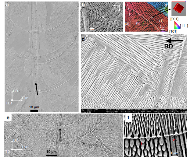
The microstructure developments due to continuous growth and side-branching in AM 316L. a Continuous growth of cells in a slender domain (highlighted by a black arrow) along the centreline across melt pools in the bi-directional scan without rotation. b–d Side-branching frequently occurred at sides of melt pools observed in all scan strategies. b Cells in (3) epitaxially grew from ones in (2) which did grow from cells in (1), and c is a corresponding inverse pole figure along TD1 of region in a. d Side-branching of cells occurred at a fusion boundary. e Continuous growth and f sidebranching (region 1) and tip-splitting (regions 1 and 2).
Scanning Strategies: The Key to Microstructural Control
The research demonstrated that laser scanning strategy selection is one of the most powerful tools for controlling microstructural development in LPBF. Different scanning patterns create different thermal histories and melt pool geometries, which in turn influence how grains grow and interact across layers.
“The role of side-branching is influential as it results in a ‘criss-cross’ layer microstructure and broadening of grains in the subsequent deposition in 3D printed alloys,” explained the authors. “In particular, side-branching is responsible for microstructure development when varying the scanning strategy.”
Comparison Table: Scanning Strategies and Their Microstructural Effects
| Scanning Strategy | Primary Growth Pattern | Side-Branching Behavior | Resulting Grain Structure | Potential Applications |
|---|---|---|---|---|
| Bi-directional Scan (No Rotation) | Continuous centerline growth | Frequent at melt pool sides | Vertical columnar grains | High-strength vertical direction |
| Chessboard Pattern (67° Rotation) | Helical epitaxial growth | Promoted out-of-layer | Helical grain structures | Isotropic properties |
| Modulated Laser Beam | Variable thermal profiles | At fusion boundaries | Mixed grain orientations | Balanced properties |
| Continuous Wave Laser | Stable melt pool | Tip-splitting regions | Consistent grain patterns | Surface finish optimization |
Helical Grain Growth: The Chessboard Strategy Breakthrough
Perhaps the most intriguing discovery in this research is the helical grain structure produced by the chessboard scanning strategy with 67° rotation between layers. This pattern breaks the vertical columnar grain microstructure typically seen in LPBF parts, replacing it with a more complex three-dimensional grain network.

Helical growth of grains in the high entropy alloy fabricated by a chessboard scan strategy. a IPF-BD map of a section along BD of HEA built by the chessboard pattern with a rotation of 67° for every subsequent layer (lower left inset). A big grain of the orientation (shown in the right cube) was able to cross several melt pools in the same layers and across multiple layers (dashed black lines highlight the boundaries of some melt pools). b Top-view of the thermal profile in a melt track predicted by FEM simulation; the unit of scale bar is K degree. c IPF-BD of a region consisting of two islands I1 and I2, being perpendicular to BD. Arrows in b and c show the moving direction of the laser beam. White dashed line in c indicate the boundaries between melt tracks. d, e Optical image and EBSD map (respectively) of a section perpendicular to BD—Note: the section was not perfectly parallel to a single layer of deposition, helping to reveal a spiral microstructure of grains across multiple layers (highlighted by white dashed lines).
“Most interestingly, the chessboard strategy with 67° rotation between layers breaks the vertical columnar grain microstructure, but it promotes both in-layer epitaxial growth and out-of-layer side branching, resulting in helical epitaxial growth. It has been shown that variations in the length-scale of microstructure correlates well with v^0.25 * G^0.5, and large pores cause a substantial coarsening of the microstructure due to their local thermal insulating effect.”
The helical grain structure is significant because it can reduce anisotropy—the tendency for materials to exhibit different properties in different directions. Conventional LPBF parts often show strong anisotropy due to the columnar grain structure that develops layer by layer. The helical pattern disrupts this vertical alignment, potentially enabling more isotropic mechanical properties without sacrificing the benefits of additive manufacturing.
Practical Applications and Industry Impact
Understanding side-branching and microstructural control has immediate practical implications for manufacturers and engineers using LPBF technology:
Aerospace Components
Critical aerospace parts requiring directional strength can benefit from controlled columnar grain structures, while components requiring isotropic properties can be produced using the chessboard strategy. The ability to tailor grain structures through scanning strategy selection provides engineers with unprecedented design flexibility.
Medical Implants
Bioimplants often need specific combinations of strength, fatigue resistance, and biocompatibility. By controlling microstructure through side-branching management, manufacturers can optimize implants for different physiological requirements and loading conditions.
Tooling and Molds
Injection molds and tooling inserts require high wear resistance and thermal stability. Understanding how side-branching affects grain boundary networks can help improve the performance and longevity of these components.
Energy Systems
Turbine blades, heat exchangers, and other energy system components operate under demanding thermal and mechanical conditions. Microstructural control through side-branching optimization can enhance performance in these applications.
Future Research Directions
While this research provides valuable insights into side-branching and microstructural control, several areas warrant further investigation:
- Multi-Material Systems: Extending the study to multi-material LPBF processes where interactions between different alloy systems could create unique microstructural phenomena
- In-Situ Monitoring: Developing real-time monitoring systems to track side-branching development during printing, enabling closed-loop control
- Process Modeling: Advanced computational models that predict side-branching behavior based on thermal history and material properties
- Mechanical Property Correlation: Establishing quantitative relationships between side-branching characteristics and mechanical performance metrics
- Machine Learning Optimization: Using AI to identify optimal scanning strategies for specific microstructural and property targets
Frequently Asked Questions (FAQ)
What is side-branching in laser powder-bed fusion?
Side-branching in LPBF is a solidification phenomenon where crystal growth extends perpendicular to the primary growth direction, creating secondary arms at the solid-liquid interface. This process occurs during the rapid cooling and solidification of melt pools and significantly influences the final grain structure and mechanical properties of 3D-printed metal parts.
How does scanning strategy affect microstructure in 3D printing?
Scanning strategy determines the thermal history and melt pool geometry during LPBF. Different patterns like bi-directional scanning, chessboard patterns, and rotated scans create different thermal gradients and cooling rates, which in turn affect side-branching behavior and grain orientation. For example, the chessboard strategy with 67° layer rotation promotes helical grain growth that breaks up vertical columnar structures.
Why is microstructural control important in additive manufacturing?
Microstructural control is crucial because the grain structure determines mechanical properties like strength, ductility, fatigue resistance, and thermal stability. By controlling microstructure through parameters like scanning strategy and thermal conditions, manufacturers can optimize parts for specific applications and achieve more consistent, predictable performance.
What are the main types of porosity in LPBF parts and how do they affect microstructure?
The three main porosity types are keyhole pores (from excessive vaporization), spherical gas pores (trapped gas from powder), and lack-of-fusion pores (insufficient melting). Large pores can cause microstructural coarsening due to their thermal insulating effect, while spherical pores tend to have less impact. Lack-of-fusion pores create sharp changes in cell spacing and disrupt solidification patterns.
How does side-branching differ between 316L stainless steel and high-entropy alloys?
The research found that both 316L and HEA exhibit similar fundamental side-branching mechanisms, including continuous growth along centerlines and frequent side-branching at melt pool boundaries. However, HEA shows additional helical growth capability when using specific scanning strategies like the chessboard pattern with layer rotation, creating more complex three-dimensional grain networks.
Can side-branching be used to reduce anisotropy in LPBF parts?
Yes, side-branching can be leveraged to reduce anisotropy. The chessboard scanning strategy with 67° rotation promotes helical epitaxial growth that breaks up vertical columnar grain structures, resulting in more isotropic properties. This provides manufacturers with a method to balance directional strength requirements with the need for uniform performance across orientations.
Conclusion
The research on side-branching in microstructure development during laser powder-bed fusion represents a significant advance in our understanding of additive manufacturing fundamentals. By revealing how scanning strategies, thermal conditions, and material characteristics interact to control solidification behavior, this work provides a roadmap for engineers seeking to optimize LPBF processes for specific applications.
As the additive manufacturing industry continues to mature, the ability to precisely control microstructure will become increasingly important for producing components that meet the demanding requirements of aerospace, medical, energy, and other critical sectors. Side-branching, once considered just another solidification phenomenon, emerges as a powerful tool in the microstructural control toolbox.
Laser powder-bed fusion has been the topic of many studies in recent years, from examining the effects of gas chemistry to achieving melt pool control, and studying innovative monitoring processes. What do you think of this research? Let us know your thoughts! Join the discussion of this and other 3D printing topics at 3DPrintBoard.com.
References:
- Chen, Y., et al. (2020). “The role of side-branching in microstructure development in laser powder-bed fusion.” Nature Communications. https://www.nature.com/articles/s41467-020-14453-3
- Thompson, S. M., et al. (2015). “An overview of Direct Laser Deposition for additive manufacturing; Part I: Transport phenomena, modeling and diagnostics.” Additive Manufacturing, 8, 36-62.
- Tong, M., & Birnbaum, A. J. (2018). “Influence of processing parameters on the quality of AlSi10Mg parts produced by DMLS.” Procedia Manufacturing, 26, 934-941.
- DebRoy, T., et al. (2018). “Additive manufacturing of metallic components – Process, structure and properties.” Progress in Materials Science, 92, 112-224.
- King, W. E., et al. (2015). “Overview of modelling and simulation of metal powder bed fusion process at Lawrence Livermore National Laboratory.” Materials Science and Technology, 31(8), 957-968.
- Yadroitsev, I., et al. (2013). “Strategy of manufacturing components with designed internal structure by selective laser melting of metallic powder.” Applied Surface Science, 268, 232-239.
- 3DPrint.com Editorial Team. (2020). “Analysis of Side Branching in Microstructure Development During Laser Powder-Bed Fusion.” 3DPrint.com.
- Wang, D., et al. (2016). “Dendrite growth in laser powder-bed fusion of metal materials.” Journal of Materials Processing Technology, 234, 161-168.
Frequently Asked Questions
What is metal 3D printing?
Metal 3D printing (additive manufacturing) builds metal parts layer by layer using techniques like laser powder bed fusion, directed energy deposition, and binder jetting. It enables complex geometries impossible with traditional manufacturing while reducing material waste significantly.
How strong are 3D printed metal parts?
3D printed metal parts can achieve mechanical properties comparable to traditionally manufactured metals. Tensile strength and fatigue resistance depend on the process and post-processing, but many meet or exceed ASTM standards for wrought materials.
What are the main metal 3D printing technologies?
The primary technologies include Laser Powder Bed Fusion (LPBF), Electron Beam Melting (EBM), Directed Energy Deposition (DED), Binder Jetting, and Metal FDM (with bound filaments). Each has different strengths in terms of resolution, speed, and material options.
📌 Related Articles
- ABS 3D Printing Settings Guide: Temperature, Enclosure, and Cooling for Strong Parts
- Creality Creality Ender 3 V3 Plus vs Creality Ender 3 Pro: Full Specs Comparison & Buyer’s Guide
- Best Budget 3D Printer Upgrades That Actually Improve Print Quality: Belts, Springs, Hotends & More
- Best 3D Printer Upgrades That Actually Improve Print Quality: Complete 2026 Guide
- Prusa Research Mini+ vs Prusa MK4: Full Specs Comparison & Buyer’s Guide